Reproducing a coadd DP0.2 galaxy image

Hi all,

I am trying to reproduce a coadd DP0 galaxy image using SLSim, an LSST-desc strong lensing simulation software. However, to reproduce a DP0 galaxy image, I need to rotate the SLSim coordinate system by a certain angle, and this angle is different for each galaxy. This indicates that the orientation difference I am observing is not due to a fixed coordinate rotation. Rather, it seems like each galaxy has its own sky rotation (though this might not be correct). If this is the case, how can I get this rotation angle? If this is not the case, what might be the issue?

I would appreciate any suggestions for this. Thank you!

Hi @nkhadka, thanks for posting this question. I don’t have the answer but I’d like to help.

Could you clarify what is meant by “coadd DP0 galaxy image”? Within Data Preview 0, deepCoadd is one of the image types, and they’re oriented north-up east-left (which makes me think you’re not attempting to reproduce a DP0 deepCoadd image, but rather something else). The individual processed visit images (calexp image types) do have a camera rotation, though.

I am unfamiliar with SLSim, or how it is being applied here, but there are no strong lensing sources in the simulation on which DP0 is based. There were some in the LSST DESC DC2 simulation, but as I understand it (from Table 1 of that paper) they were in the deep drilling fields, and DP0 is based only on the wide-fast-deep fields.

Hi @MelissaGraham ,

Thank you very much for your reply!
A coadd DP0 galaxy image refers to a DP0 deepCoadd galaxy image. For a DP0.2 galaxy, if we use the given Sersic profiles, ellipticity, and deepCoadd image properties (background noise, Poisson noise, PSF) for a DP0 galaxy, we should be able to produce an image that is very close to the DP0 deepCoadd galaxy image. However, I am noticing an orientation difference between the SLSim-generated galaxy image and the DP0 deepCoadd image of the same galaxy.

Hi @MelissaGraham the issue is not just with SLSim, even when using Galsim with the ellipticity orientations in the catalogue, the images are not aligned and require DIFFERENT relative rotations from image to image. Just wanted to add this here. Correct me if I am wrong @nkhadka

Thanks @sibirrer for adding this information! You are correct.

Each LSST simulated image has a different orientation with respect to the sky. I.e., a different translation+rotation matrix from x, y on the detector to RA, Dec on the sky. This means that position angle in detector coordinates is different than position angle on the sky. I would thus expect that for each image a galaxy requires a different relative rotation in detector coordinates to place correctly on a given calexp.

Could you perhaps post some pseudo code illustrating the problem? I’m not sure we’re yet sharing a common understanding of the terms and the problem, and the more concrete we can make the example, the more helpful we can be.

Based on @nkhadka’s reply, it sounds like we’ve established that you’re using the DP0.2 deepCoadd images (i.e., accessible either via the butler or TAP services provided by the Rubin Science Platform).

@nkhadka and @sibirrer, could you clarify when you say “if we use the given Sersic profiles, ellipticity …” and “the ellipticity orientations in the catalogue”, exactly what catalog and columns you are using. The DP0.2 Object table contains photometry and shape measurements on those deepCoadd images, but the DP0.2 Object table schema does not explicitly have a column for “Sersic profile” (but does have ellipse parameters). Where are “the given Sersic profiles” coming from?

Thanks @mwv, I agree. A bit of code that demonstrates which data you’re accessing, and what the expectation is vs. the issue you’re reporting, would be helpful.

Thank you very much @mwv for your reply!

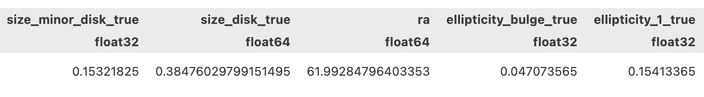
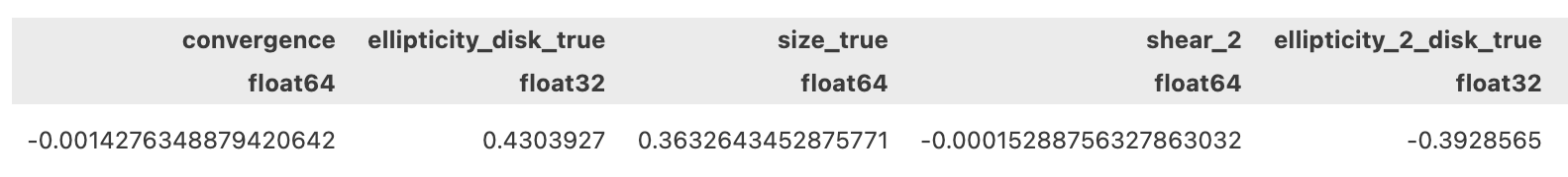
@MelissaGraham , you are correct, we are using deepCoadd image. We got all the parameters of a selected galaxy from the DC2 catalog. Screen shots of some of the parameters of a selected galaxy are given below:


As @mwv aksed, here is a piece of code that I have used to generate these images:

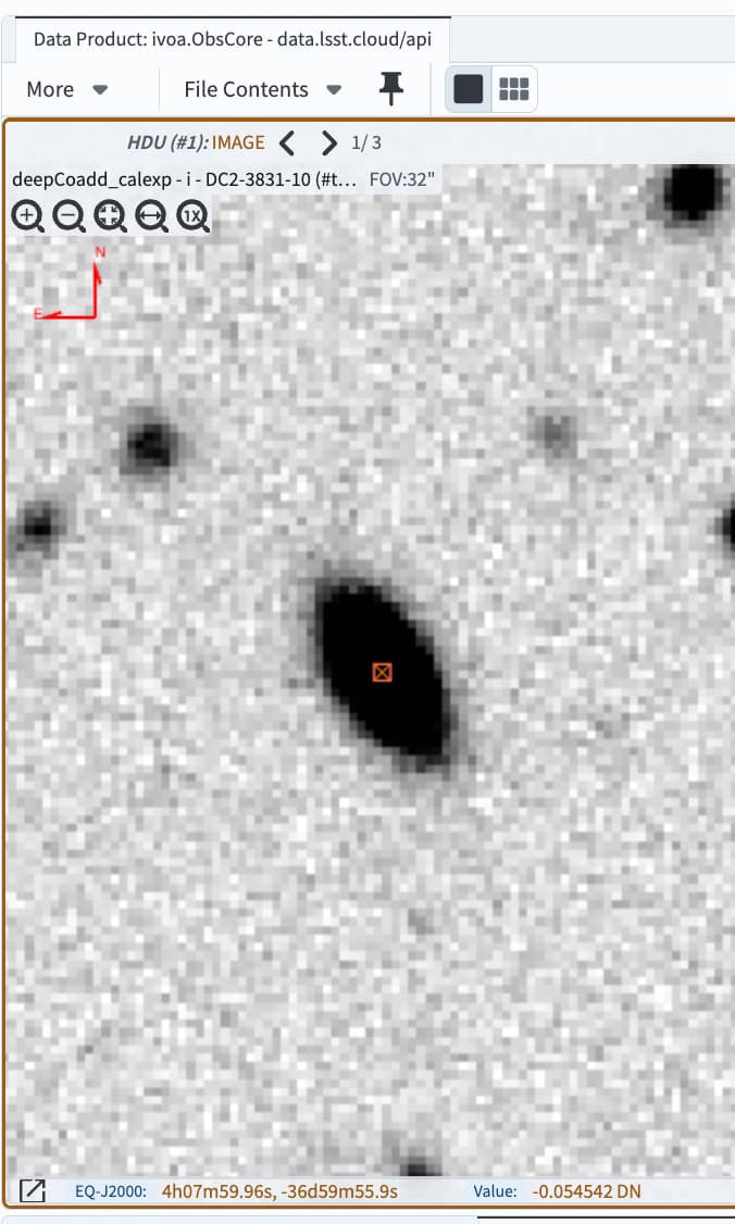
I made a cutout (35*35 pixel) image of a galaxy at ra=61.999855458880795 and dec=-36.99883611551307. This cutout is from the deepCoadd image.

Then, I used following information of this galaxy from the DC2 catalog to generate an image using slsim:

position angle

position_angle=np.pi*dc2_galaxies[2][“position_angle_true”]/180

axis ratios of disk dominated galaxy

q_disk=dc2_galaxies[2][‘size_minor_disk_true’]/dc2_galaxies[2][‘size_disk_true’]
q_bulge=dc2_galaxies[2][‘size_minor_bulge_true’]/dc2_galaxies[2][‘size_bulge_true’]
q = dc2_galaxies[2][‘size_minor_true’]/dc2_galaxies[2][‘size_true’]

Disk dominated galaxy

epsilon_disk=(1-q_disk)/(1+q_disk)
epsilon_bulge=(1-q_bulge)/(1+q_bulge)
epsilon = (1-q)/(1+q)

disk dominated

e1_disk = epsilon_disk * np.cos(2 * position_angle)
e2_disk = epsilon_disk * np.sin(2 * position_angle)
e1_bulge = epsilon_bulge * np.cos(2 * position_angle)
e2_bulge = epsilon_bulge * np.sin(2 * position_angle)
e1 = epsilon * np.cos(2 * position_angle)
e2 = epsilon * np.sin(2 * position_angle)

#SLSim kwargs for a disk dominated galaxy. Here, we use
kwargs_lens_1 = [{‘theta_E’: 1,
‘gamma’: 2,
‘e1’: e1,
‘e2’: e2,
‘center_x’: center_cood_x_1,
‘center_y’: center_coord_y_1},
{‘gamma1’: dc2_galaxies[2][“shear_1”],
‘gamma2’: dc2_galaxies[2][“shear_2”],
‘ra_0’: 0,
‘dec_0’: 0},
{‘kappa’: dc2_galaxies[2][“convergence”], ‘ra_0’: 0, ‘dec_0’: 0}]
kwargs_source_1= None
flux_i_1 = 10 ** (-dc2_galaxies[2][“mag_true_i_lsst”] / 2.5)
mag_bulge_i_1 = -2.5 * np.log10(dc2_galaxies[2][“bulge_to_total_ratio_i”] * flux_i_1)
mag_disk_i_1 = -2.5 * np.log10((1-dc2_galaxies[2][“bulge_to_total_ratio_i”]) * flux_i_1)
kwargs_lens_light_i_1 = [{‘magnitude’: mag_bulge_i_1,
‘R_sersic’: dc2_galaxies[2][“size_bulge_true”],
‘n_sersic’: 4.0,
‘e1’: e1_bulge,
‘e2’: e2_bulge,
‘center_x’: center_cood_x_1,
‘center_y’: center_coord_y_1},
{‘magnitude’: mag_disk_i_1,
‘R_sersic’: dc2_galaxies[2][“size_disk_true”],
‘n_sersic’: 1.0,
‘e1’: e1_disk,
‘e2’: e2_disk,
‘center_x’: center_cood_x_1,
‘center_y’: center_coord_y_1}]
flux_r_1 = 10 ** (-dc2_galaxies[2][“mag_true_r_lsst”] / 2.5)
mag_bulge_r_1 = -2.5 * np.log10(dc2_galaxies[2][“bulge_to_total_ratio_i”] * flux_r_1)
mag_disk_r_1 = -2.5 * np.log10((1-dc2_galaxies[2][“bulge_to_total_ratio_i”]) * flux_r_1)
kwargs_lens_light_r_1 = [{‘magnitude’: mag_bulge_r_1,
‘R_sersic’: dc2_galaxies[2][“size_bulge_true”],
‘n_sersic’: 4.0,
‘e1’: e1_bulge,
‘e2’: e2_bulge,
‘center_x’: center_cood_x_1,
‘center_y’: center_coord_y_1},
{‘magnitude’: mag_disk_r_1,
‘R_sersic’: dc2_galaxies[2][“size_disk_true”],
‘n_sersic’: 1.0,
‘e1’: e1_disk,
‘e2’: e2_disk,
‘center_x’: center_cood_x_1,
‘center_y’: center_coord_y_1}]
flux_g_1 = 10 ** (-dc2_galaxies[2][“mag_true_g_lsst”] / 2.5)
mag_bulge_g_1 = -2.5 * np.log10(dc2_galaxies[2][“bulge_to_total_ratio_i”] * flux_g_1)
mag_disk_g_1 = -2.5 * np.log10((1-dc2_galaxies[2][“bulge_to_total_ratio_i”]) * flux_g_1)
kwargs_lens_light_g_1 = [{‘magnitude’: mag_bulge_g_1,
‘R_sersic’: dc2_galaxies[2][“size_bulge_true”],
‘n_sersic’: 4.0,
‘e1’: e1_bulge,
‘e2’: e2_bulge,
‘center_x’: center_cood_x_1,
‘center_y’: center_coord_y_1},
{‘magnitude’: mag_disk_g_1,
‘R_sersic’: dc2_galaxies[2][“size_disk_true”],
‘n_sersic’: 1.0,
‘e1’: e1_disk,
‘e2’: e2_disk,
‘center_x’: center_cood_x_1,
‘center_y’: center_coord_y_1}]
kwargs_ps_1 = None

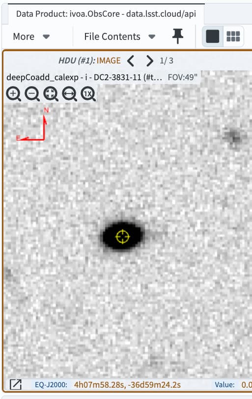
Then we generate an image using lens_image() function in slsim: slsim/slsim/image_simulation.py at 68adf909194f9114f0692764f7d4361c5001cc6e · LSST-strong-lensing/slsim · GitHub

Variance map, psf, and zeropoint are used from the deepCoadd cutout image.
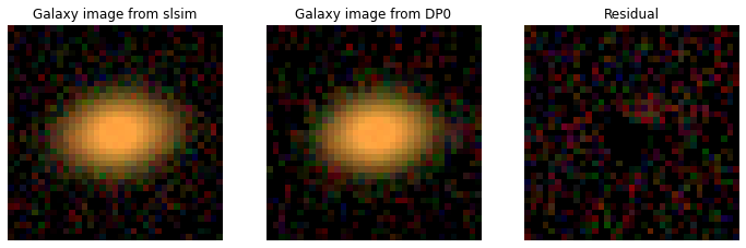
Image comparision with the actual position angle:
image_comparision_with_actual_postion_angle_from_catalog
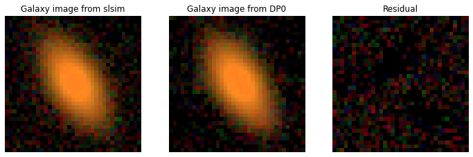
image comparision with the position angle rotated by 140 degree:
dc2_2_comp_variance_2

For full tutorial, please see: https://app.reviewnb.com/LSST-strong-lensing/slsim/pull/163/

Thank you!

Hi @nkhadka,

If I use the Portal Aspect of the Rubin Science Platform (RSP) to find your galaxy, and display the i-band deeply coadded image with north up, east left, it does match the orientation you expect.

Screenshot:

Looking at the linked tutorial, it appears that the image labeled “Galaxy image from DP0” are being loaded from .npy files? Somewhere along the line I’d guess the image orientations are being rotated (or perhaps just flipped or transposed), maybe when those files are read or written?

If you might instead like to use the RSP’s image cutout service, which returns DP0 stamps with WCS, there is a tutorial for that. It is designed to be run from within the RSP but can be adapted (e.g., with use of an authorization token) to run from elsewhere. Let me know if that might be useful?

Hi @MelissaGraham , thanks for doing this! I apologize for giving incorrect ra and dec. These images are for the galaxy given in screen shot. For this galaxy, ra, dec = 61.99284796403353, -36.9900209621661. Yes, I loaded Galaxy image from DP0 from a saved file. This image is obtained from the deepCoadd images using butler. It would be great if you could query this galaxy and see if orientation matches.

OK yes, with coordinates ra, dec = 61.99284796403353, -36.9900209621661 instead, the image does match yours labeled “Galaxy image from DP0”.

I can see in the table of truth parameters that the disk of this galaxy had E1 = 0.176 and E2 = -0.393, which should lead to an orientation like you show in the “Galaxy image from slsim” (like in this plot, right?).

Since this seems to be a question about the simulation (DC2, by DESC) and not the processing (DP0, by Rubin), I’ll try to find someone who can answer your question.

Thanks, @MelissaGraham. Yes, the orientation of the DP0 image should match the SLSim image or be rotated by a fixed angle (e.g., 90 or 180 degrees) if there is a difference in the coordinate convention, but this is not the case. This might also be related with the deepCoadd processing pipeline. I hope someone will be able to point out the solution.

Are the various relative rotation angles that you are finding consistent with a flip in the sign convention for the position angle? For the DC2 image sims, we used a position angle convention that was used by the phosim code, whereas codes like treecorr define the sign of the PA wrt Celestial North in the opposite sense. Here’s the PR in GCRCatalogs where we switched conventions (well after the DC2 sims).

1 Like

Thank you very much @jchiang for your suggestion! After your suggestion, I explored DC2 catalog. DC2 catalog has 3 different position angles. One is position_angle_true. I think this one is in galsim convention. Another one is position_angle_true_posim. This is -ve of position_angle_true and I believe this is the convenstion for posim. The last one is position_angle_true_dc2. I am not sure how this angle is derived. I used this angle and found match with DP0 images. So, position angle used in DP0 images is position_angle_true_dc2.

Thanks all for your help. I have attached some cmparisions.
7b9ceab4-5098-40f5-ad5b-84d83a012796
ec69eae6-e69b-4dfc-b724-b59e8cb83deb

2 Likes